The CG is not guessed. It is placed relative to stability.
The center of gravity is the balance point of the airplane.
It is the point where the airplane’s weight can be treated as acting. If you support a small model at that exact location, it will sit level instead of tipping nose-down or tail-down. That simple physical test explains why the CG matters so much: it is not just a measurement on the workbench. It is the mass reference the airplane carries into flight.
But the CG should not be chosen from the nose, from looks, or from a fixed percentage copied from another airplane.
A CG position only makes sense when it is placed relative to the airplane’s stability reference.
For pitch balance, that reference is the neutral point.
The neutral point is the aft pitch stability limit of the airplane. If the CG moves too close to it, the airplane becomes less self-correcting. If the CG moves behind it, the airplane can become unstable.
So the useful design question is not: where should the CG be?
It is: where is the neutral point?
Once the neutral point is estimated, the CG can be placed ahead of it with the right amount of static margin.
Start with aerodynamic centers
The graphical method starts with two aerodynamic reference points: one for the wing, one for the horizontal tail.

For most conventional subsonic wings, early design uses a simple approximation: the wing aerodynamic center sits near the quarter-chord point, about 25% of the Mean Aerodynamic Chord back from the leading edge.
This does not mean all the lift physically comes from that point. Real lift is distributed across the wing. The useful thing about the aerodynamic center is that, around this point, changes in angle of attack do not significantly change the pitching moment. That makes it a stable reference for balance work.
The horizontal tail also has an aerodynamic center. For early design, mark it at about 25% of the horizontal tail’s mean chord.
These two points are not centers of gravity. They are aerodynamic reference points. The next step is to combine them.
Build the neutral point
To estimate the neutral point, do not average the wing aerodynamic center and the tail aerodynamic center by eye.
Find their barycenter using their effective surfaces.
The wing uses its real surface. The horizontal tail is reduced by an efficiency factor. A practical first estimate is to count the tail as half its real surface. This correction keeps the method realistic without making it too heavy. The tail does not work in the same conditions as the wing. It has its own aspect ratio, its own efficiency, and it sits in the wing’s wake. Counting it at half surface gives a usable first approximation.
Graphically, the logic is:
Wing aerodynamic center → weighted by wing area

Horizontal tail aerodynamic center → weighted by 0.5 × tail area

Wing + tail reference → barycenter of both weighted points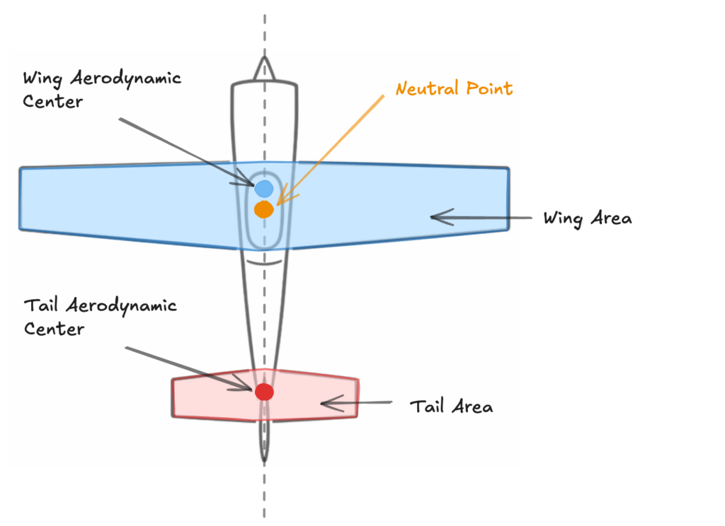
This gives the wing-and-tail stability reference.
The fuselage also contributes to pitch behavior. It is not usually the main active surface, but it is not neutral either. In early design, its effect can be handled as a simple correction: move the wing-and-tail reference forward by about 5% of the Mean Aerodynamic Chord.
Neutral point ≈ wing-and-tail reference shifted forward by 5% MACThis gives a first estimate of the airplane’s neutral point.
The exact value can be refined later, but the important thing is the method. The CG is not chosen first. The neutral point is estimated first.
Center of Gravity and Static Margin
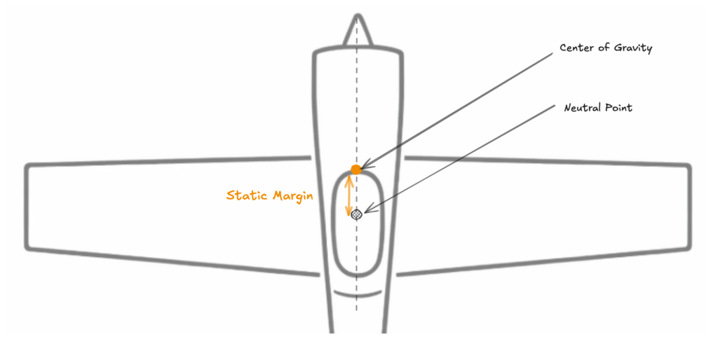
Once the neutral point is estimated, the first-flight CG is placed forward of it.
The distance between the CG and the neutral point is the static margin. In practice, it is usually expressed as a percentage of the Mean Aerodynamic Chord.
For a first flight, place the CG at least 5% of MAC ahead of the neutral point. Increase that margin for a more forgiving trainer-style setup. This gives the airplane a positive static margin. It does not guarantee perfect trim, but it gives the design a safer starting point than guessing a generic CG range.
This also explains why two airplanes with the same wing can need different CG positions. If the tail is larger, smaller, farther back, or closer to the wing, the neutral point moves. If the fuselage is long or influential, the neutral point moves again. When the neutral point moves, the CG must move with it.
That is the real value of the graphical method. It does not give you a magic number. It gives you a design relationship.
Static margin is the room you leave between balance and neutrality.
More static margin means the CG sits farther ahead of the neutral point. The airplane becomes more stable and more self-correcting, but it may also feel heavier in pitch. It may need more elevator authority to rotate, flare, or hold a slow attitude.
Less static margin means the CG moves closer to the neutral point. The airplane becomes more responsive, but also less self-correcting. That can be useful for advanced flying, but the price is clear: the airplane gives less help. The pilot must manage more of the stability by hand.
If the CG moves too far back, the margin disappears. The airplane may no longer recover naturally from pitch disturbances. It can become sensitive, difficult to trim, prone to abrupt stall behavior, or simply unpleasant to fly. At that point, the problem is not that the airplane lacks enough elevator. The problem is that the basic balance has crossed into an unsafe region.
Use static margin as a tuning reference, not as a universal rule. The useful number depends on how the neutral point is estimated, the tail volume, the airplane type, the airfoil, and the pilot’s intent.
These values define mission-consistent ranges, not fixed targets.
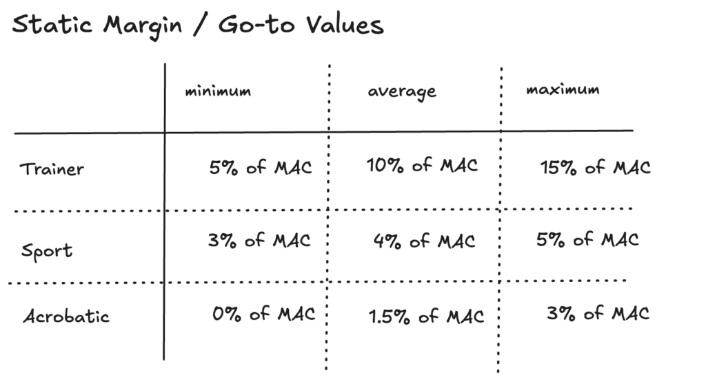
The numbers are less important than the direction of the trade-off.
More margin gives more stability. Less margin gives more response. Too little margin is not automatically better performance. It may only make the airplane unstable and tiring to fly.
A good first-flight strategy is simple: start with a margin that gives the airplane some reserve, then move the CG gradually during test flights if the airplane proves too stable, too heavy in pitch, or too reluctant to maneuver.
What CG changes in flight
Once the airplane is in the air, the wing, tail, and control surfaces all work around the center of gravity.
A forward CG gives the airplane more stability reserve, but it can also make pitch feel heavier. An aft CG reduces that reserve. It may feel more responsive at first, but recovery becomes harder and stall behavior becomes less forgiving.
That is why the CG cannot be chosen independently. It must work with the wing, the tail, the fuselage, and the static margin.
Balance is not only about making the airplane sit level on your fingers. It is about placing the airplane’s mass far enough ahead of its stability limit that the aerodynamic forces can control it.
The method can be remembered in one sequence:
1. Mark the wing and tail aerodynamic centers.
2. Resolve the neutral point graphically.
3. Apply the fuselage correction.
4. Place the first-flight CG ahead of the neutral point.
5. Tune with static margin after flight testing.
That is when balance becomes a design decision, not a guess.
At this point, the airplane has an aerodynamic reference, a mass reference, and a stability margin. But it still has to sit, roll, rotate, and land on the ground. That is where landing gear turns balance into usable geometry.
RC Plane Designer evolves as chapters are refined and connected.
The project began as a personal notebook used while designing scratch-built RC airplanes.
If you are learning from it or building with it, your feedback helps shape what comes next.
Follow the project or get in touch.