The airfoil defines how the wing behaves in the air, long before the pilot touches the controls.
So far, the wing has been defined primarily by its planform geometry. Span, surface, taper, and sweep determine how lift is distributed along the wing.
But the wing is more than its planform.
The wing’s cross-section, the airfoil, determines how the wing generates lift and how it responds to changes in angle of attack.
Three parameters define this aerodynamic behavior: airfoil shape, relative thickness, and angle of incidence.
Together, they determine how lift builds, how the wing approaches stall, and how predictable the airplane feels in flight.
Airfoils Families
Two wings with identical span, surface, and sweep can behave very differently simply because their airfoil sections are different.
In practice, most RC airplanes rely on four broad airfoil families. These form a progression from highly cambered profiles optimized for slow flight to neutral profiles suited for precision and aerobatics.
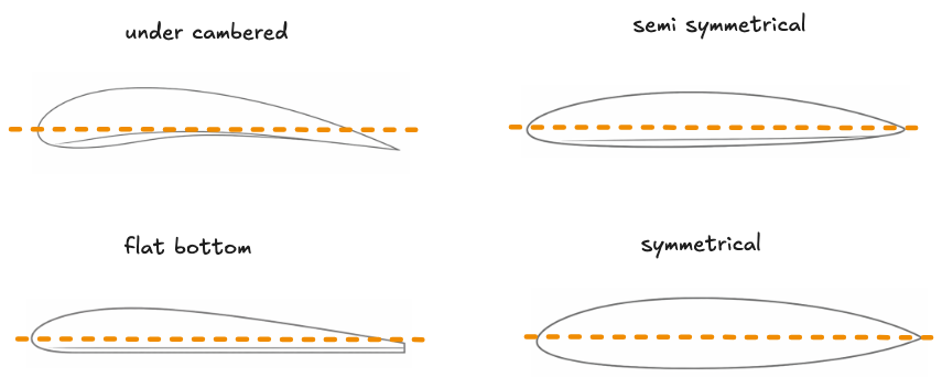
Under-cambered airfoils generate strong lift at low speeds and work well at the low Reynolds numbers typical of model airplanes. They are commonly used on gliders, vintage aircraft, and slow flyers where maximum lift and gentle stall behavior are priorities. The trade-off is higher drag and reduced structural stiffness, which limits their suitability for faster airplanes.
Flat-bottom airfoils generate lift easily and tend to stall progressively. Their forgiving behavior makes them well suited for trainer airplanes, offering reliable low-speed performance while remaining simple to build.
Semi-symmetrical airfoils provide a balanced compromise between lift generation and aerodynamic efficiency. They generate moderate lift at low speeds while remaining efficient across a wider speed range, which explains why they are widely used on sport airplanes.
Symmetrical airfoils produce nearly identical aerodynamic behavior upright and inverted. They are therefore preferred for aerobatic airplanes, where neutral handling and precise control are more important than maximizing low-speed lift.
Greater camber generally favors slow flight and forgiving stall behavior, while more neutral profiles favor speed, precision, and aerobatic performance.
Once the airfoil family is selected, the next parameter to consider is how thick the airfoil is relative to the chord.
Relative Thickness
Beyond airfoil shape, relative thickness also influences how the wing behaves.
Relative thickness is the ratio between the airfoil’s maximum thickness and its chord length, usually expressed as a percentage.
Relative thickness (t/c) = maximum thickness / chordThicker airfoils generally generate lift more easily at low speeds, stall more progressively, and provide greater structural depth for spars. Thinner airfoils tend to reduce aerodynamic drag, allow higher speeds, and produce sharper aerodynamic response.
In practice, relative thickness must balance aerodynamic behavior with structural and construction constraints. Designers often combine both advantages by using thicker sections near the wing root for strength while reducing thickness toward the tip.
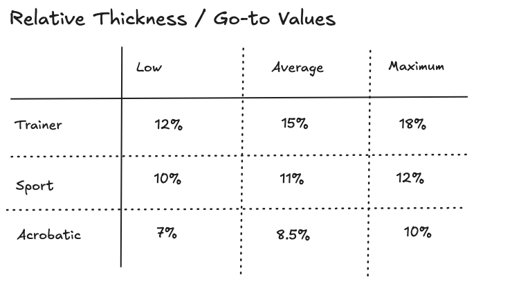
Trainer airplanes favor thicker airfoils because they support low-speed flight and forgiving stall behavior. Sport airplanes typically operate in a moderate range that balances efficiency and maneuverability. Aerobatic designs often use thinner airfoils to reduce drag and improve maneuver precision.
Once the airfoil shape and its thickness are defined, the next step is to determine how the wing is installed on the airplane.
Angle of Incidence
Lift depends on the angle between the wing and the airflow, known as the angle of attack. This angle constantly changes during flight as the pilot adjusts the airplane’s pitch.
Designers do not set angle of attack directly. They set the wing’s angle of incidence.
Angle of incidence is the fixed angle between the wing chord line and the airplane’s reference axis. It defines how the wing is mounted on the airplane.
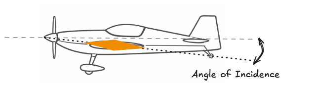
By setting this angle, the designer determines how much lift the wing naturally produces during normal flight. A small positive incidence allows the wing to generate lift while the fuselage remains nearly level in cruise, improving flying comfort.
Trainer airplanes typically use slightly higher incidence so the wing produces lift easily at low speeds. Aerobatic airplanes usually use smaller angles so the airplane flies cleanly with minimal drag.
Once the wing section and its installation angle are defined, the wing is aerodynamically complete. What remains is not how lift is produced, but how it is controlled across the span.
What Airfoils Define and What Remains Open
At this stage, the wing’s aerodynamic behavior is largely defined.
Planform geometry determines how lift is distributed along the span.
The airfoil and its thickness determine how lift is produced.
Incidence defines how the wing naturally carries the airplane in normal flight.
But producing lift is only part of the story.
An airplane must also control lift asymmetrically in order to maneuver. By increasing lift on one wing and reducing it on the other, the airplane generates a rolling moment.
This is the role of the ailerons.
The next chapter examines how aileron position and surface area influence roll authority, responsiveness, and overall handling.
RC Plane Designer evolves as chapters are refined and connected.
The project began as a personal notebook used while designing scratch-built RC airplanes.
If you are learning from it or building with it, your feedback helps shape what comes next.
Follow the project or get in touch.